Wireless charging for electric buses is based on inductive power transfer, a method that allows electrical energy to pass between two coils without direct physical contact.
The principle is closely related to that used in smaller consumer devices, but scaled significantly to handle the higher power demands of public transport vehicles.
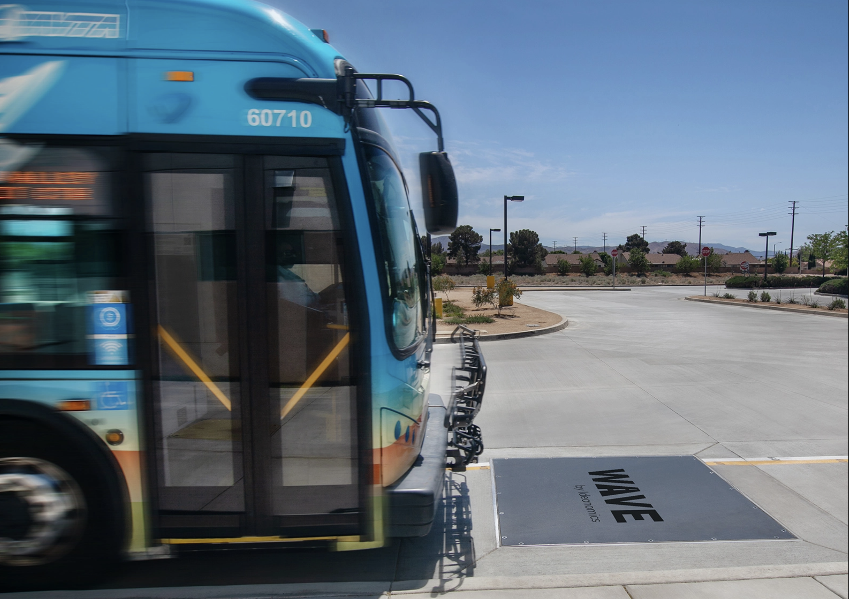
At its core, the system relies on electromagnetic fields. A primary coil is embedded in the road surface or at a designated charging pad, while a secondary coil is installed underneath the bus. When alternating current passes through the ground-based coil, it generates a magnetic field. This field induces a current in the vehicle-mounted coil, which is then converted into direct current to charge the battery.
This process is typically described by the physics of electromagnetic induction, where a changing magnetic field produces an electric current in a nearby conductor.

In this expression, V represents the induced voltage and Φ the magnetic flux. The efficiency of energy transfer depends on how effectively the magnetic field links the two coils. d stands for a differential, meaning a very small change in a quantity, while t stands for time.
The equation thus refers to the rate of change of magnetic flux (Φ) with respect to time. It describes how quickly the magnetic field linking the coil is changing, and that change is what generates the voltage.
A wireless charging installation for buses generally consists of three main elements:
Ground infrastructure: This includes the embedded coil, power electronics and grid connection. The system converts grid electricity into high-frequency alternating current suitable for induction.
Vehicle equipment: A receiving coil mounted under the bus, along with rectifiers and control systems, converts the induced current into a form suitable for battery charging.
Control and communication systems: These ensure that charging only occurs when a vehicle is correctly positioned and authorised, and that power transfer is regulated safely.
Charging pads are often installed at bus stops, termini or depots. In most designs, charging currently occurs only when the bus is stationary.
Power Levels
Wireless charging systems for buses typically operate in the range of 50 kW to over 300 kW, depending on the application.
Efficiency is a key technical consideration. Modern systems can achieve efficiencies of around 85–95 percent under optimal alignment conditions. However, misalignment between the ground and vehicle coils can reduce efficiency, leading to energy losses. To address this, guidance systems, either visual, automated or sensor-based, are used to help drivers position the bus accurately.
Because inductive charging involves high currents and magnetic fields, thermal management is important. Both ground and onboard components may require cooling systems to prevent overheating during repeated charging cycles.
Safety mechanisms are also integral. Systems are designed to detect foreign objects, such as metal debris, that could heat up in the magnetic field. Charging is automatically interrupted if anomalies are detected. In addition, electromagnetic field exposure is regulated to remain within established public safety limits.
Integration with Operations
Wireless charging changes how electric buses are deployed. Instead of relying solely on large onboard batteries charged overnight, operators can use smaller batteries supplemented by frequent charging throughout the day. This can reduce vehicle weight and increase passenger capacity.
However, the approach requires careful route planning and infrastructure investment. Charging points must be located where buses naturally stop long enough to receive meaningful energy transfer. The system must also be integrated with scheduling to avoid delays.
Comparison with Conductive Charging
Conventional conductive charging, using plug-in cables or overhead pantographs, remains more widespread. These systems generally offer higher peak efficiencies and lower installation costs. Wireless charging, by contrast, reduces physical wear and removes the need for exposed connectors, which can be beneficial in adverse weather conditions or high-frequency operations.
However, inductive systems tend to involve higher upfront infrastructure costs and slightly lower efficiency. Their adoption is therefore often linked to specific operational requirements, such as routes with frequent stops or environments where minimising visible infrastructure is desirable.